Why a boat lift cannot be reduced to one horsepower entry
A complete boat lift may contain more than one motor. The electrical model also depends on motor voltage and phase, the circuit feeding the lift, the distance to the controller, the actual listed equipment overcurrent protection, controller-supply conductors, controller-to-motor conductors, accessory receptacles, and the number of complete lifts that can operate at one time.
Those details affect different parts of the marina calculation. A same-slip shore-power comparison affects the selected-edition marina demand workflow. The motor branch still needs its own conductor, protection, grounding, voltage-drop, and equipment review. Upstream feeders may need to account for multiple lifts and a governing largest-motor treatment.
1. Identify one complete lift and the slip it serves
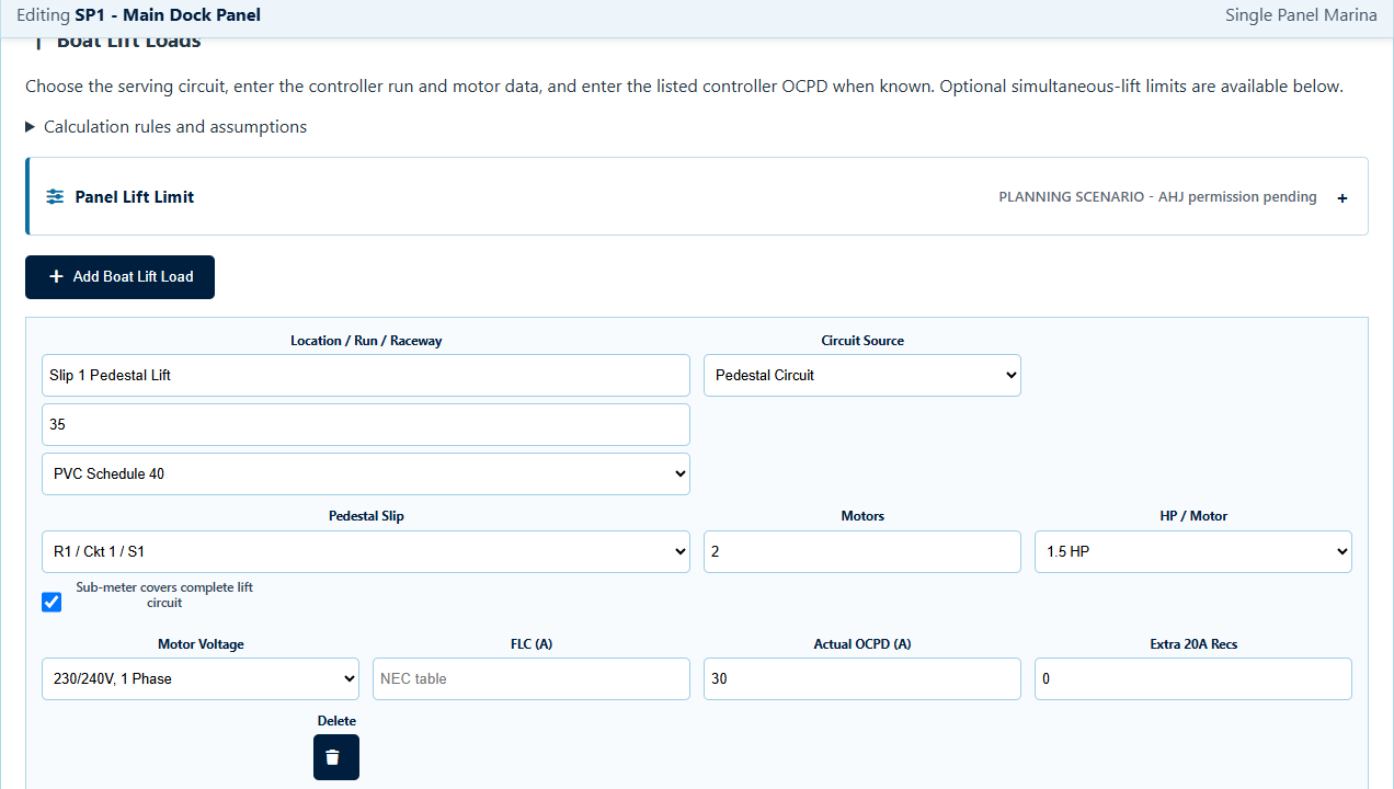
Start with one lift per slip. Identify the dock, pedestal side, or serving panel circuit associated with that complete lift. This prevents separate motors on the same lift from being mistaken for independent lifts that can be diversified against each other.
Record a clear lift name and slip identifier so the same equipment can be recognized in the input table, panel schedule, one-line, motor review, and PDF report.
2. Choose the actual source topology
The source selection changes how the load enters the distribution model. Two common arrangements are:
- Pedestal Circuit: the lift is associated with a selected pedestal feeder and can participate in the selected-edition same-slip load comparison.
- Serving Panel Circuit: the lift receives an independent panel circuit and does not require a pedestal selection.
Do not choose a topology only to obtain a smaller demand result. The software model has to match the actual one-line and intended installation.
3. Enter the motor characteristics
For every motor on the complete lift, record the horsepower, voltage, phase, and frequency as applicable. If the software uses a code-table FLC basis, compare the result against the actual equipment and manufacturer information. A nameplate current or listed-controller requirement can govern a real installation even when a planning tool begins with standard table values.
ShorePowerCalc supports single-phase lift motors and 208V three-phase motors within the available workflow. It applies source-aware voltages, calculates planning values from the entered motor configuration, and states the underlying assumptions in the report.
4. Preserve the controller and OCPD information
The controller or listed lift equipment is a critical part of the branch review. Enter the actual equipment branch OCPD when it is known and valid for the selected configuration. If it is not known, treat a calculated range or maximum as preliminary and verify the final value against the equipment listing and manufacturer instructions.
The protection type matters. An input that assumes an inverse-time circuit breaker should not be reused for a fuse, instantaneous-trip device, or other protection type without a separate review.
Manufacturer data controls. Boat-lift controller markings, motor data, terminal temperature ratings, overcurrent requirements, and installation instructions can change the final branch and feeder design.
5. Size the local branch and controller-to-motor conductors
The source-to-controller branch and the conductors from the controller to each motor are different calculation paths. Keep them separate in the project record.
A planning report should show the controller-supply conductor basis, controller-to-motor conductor results, equipment grounding conductor, entered distance, and voltage drop. It should also disclose the assumed conductor material, wiring method, terminal temperature basis, and conductor-grouping limits.
6. Handle accessory receptacles explicitly
If the lift location includes an extra 20A service or accessory receptacle, identify whether it is already part of the pedestal layout or is an additional load. Duplicating the same receptacle in both places can overstate the project load.
When the lift is panel-fed, an accessory receptacle may require a separate branch instead of being combined with the motor branch. Keep the circuit relationship visible in the schedule and one-line.
7. Use simultaneous-lift limits only with a defensible basis
A maximum simultaneous-lifts setting applies between complete lifts. It should not fractionally reduce the motors that make up one complete lift. If fewer than all connected lifts are assumed to operate, document the operating control, interlock, management procedure, or other project basis and obtain the required professional and AHJ acceptance.
On a project with downstream panels and an upstream MDP, preserve both the downstream panel limit and any separate marina-wide limit. Do not compound those assumptions in a way that reduces the same motor load twice.
8. Review the motor load at every upstream feeder
A lift branch can be acceptable while an upstream feeder remains unresolved. Follow the motor load through the selected pedestal feeder, dock panel, MDP, or substation arrangement as applicable.
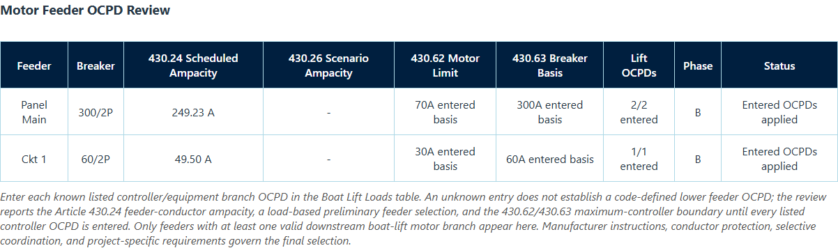
The upstream review should retain the motor-feeder ampacity floor and show whether the feeder OCPD review is based on valid actual downstream controller protection or an unresolved range. The final feeder breaker also depends on conductor protection, equipment ratings, selective coordination, manufacturer information, and project-specific engineering.
9. Reconcile the schedule, one-line, and PDF
After calculating, confirm that every lift appears at the correct source in the panel schedule and one-line. For a pedestal-fed lift, the diagram should make its pedestal relationship clear. For a panel-fed lift, the separate circuit should remain visible. Compare the report's connected-lift count, simultaneous-lift count, basis note, branch results, and upstream feeder review against the input table.
Complete review chain: lift and slip identity, source topology, every motor, controller and actual OCPD, branch distance, conductor and EGC results, accessory receptacles, simultaneous-operation basis, upstream feeders, schedules, and one-line.
What ShorePowerCalc does and does not do
ShorePowerCalc organizes boat-lift motor inputs and planning calculations across Single Panel, Multi Panel, and Large MDP & Substation marina modes. It carries the selected lift topology into schedules, tagged vertical one-lines, saved projects, and PDF reports.
It does not select actual equipment, verify a controller listing, perform a short-circuit or coordination study, determine available fault current, resolve ground-fault protection, inspect field routing, or replace the engineer of record, manufacturer, utility, and AHJ.