
Begin with the adopted edition and project authority
NEC Article 555 addresses marinas, boatyards, floating buildings, and docking facilities. The exact calculation references, table designations, wording, and local requirements can vary by edition and jurisdiction. Before building the load model, confirm the edition adopted for the project, the effective date, local amendments, utility criteria, manufacturer requirements, and the authority having jurisdiction.
ShorePowerCalc provides selectable 2023 and 2026 marina demand calculation bases. That selection organizes the software's calculation path; it does not decide which edition legally applies to a specific site.
Do not treat this page as a code interpretation. It is a workflow checklist. The adopted NEC edition, local amendments, engineer of record, qualified professionals, utility, equipment manufacturer, and AHJ control the final project decisions.
1. Define the distribution hierarchy
Identify the point where the marina calculation starts and every distribution level the project needs to represent. Common arrangements include:
- One 120/240V or 120/208V marina panel feeding pedestal circuits.
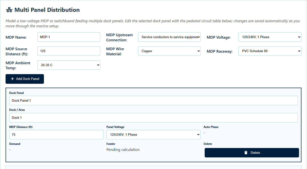
- A low-voltage MDP or switchboard feeding multiple dock panels.
- A 480/277V landside MDP feeding 480V single-phase marine substations and downstream 120/240V pedestal panels.
This hierarchy affects how demand is aggregated, where feeders are sized, how phase loading is organized, and what the one-line diagram must show. A spreadsheet designed around one panel can become difficult to audit when the project grows to multiple dock panels or substations.
2. Inventory shore-power receptacles by slip and location
Count and classify the shore-power receptacles actually served by each panel or feeder. Keep the receptacle layout associated with its pedestal side or slip instead of entering only a project-wide total. That relationship matters when the selected-edition marina demand table includes rules based on the receptacles serving an individual slip.
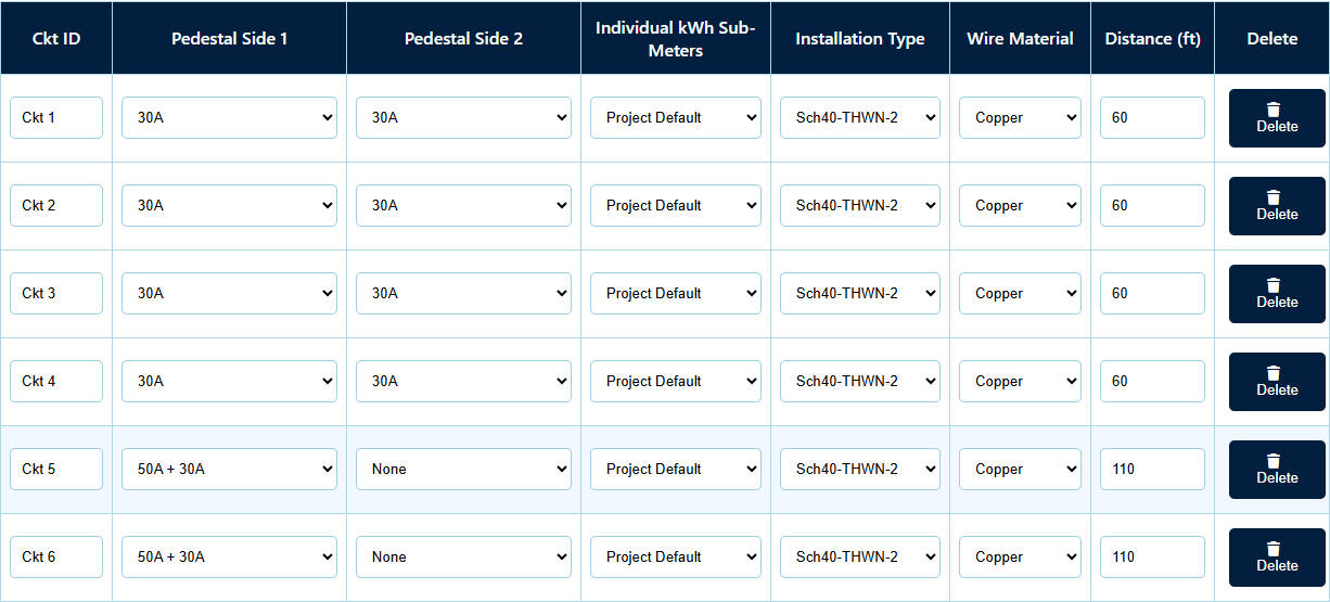
For each pedestal circuit, record:
- A stable circuit ID that will also appear in schedules and diagrams.
- The receptacle combination on each pedestal side.
- Whether a convenience or accessory receptacle is separate from the shore-power demand count.
- The wiring method and conductor material.
- The source-to-first-pedestal distance and any additional loop spans.
- Any nonstandard receptacle or custom-load information that requires manual review.
Do not lose the difference between a pedestal location, a pedestal side, an individual slip, and a feeder circuit. Those terms can represent different counting and documentation concepts.
3. Document demand-factor inputs instead of only the result
A calculated demand is easier to review when the report shows the receptacle count, selected calculation basis, demand factor, individual sub-meter setting, and any same-slip or special handling applied by the software.
If the project relies on an edition-dependent reduction, note, or special condition, preserve the reason in the calculation package. A reviewer should not have to reverse-engineer the demand total to determine whether a reduction was used.
For multi-panel and large-marina arrangements, verify that upstream demand is based on all qualifying downstream shore-power receptacles at that calculation boundary. Simply adding independently diversified downstream panel totals may not represent the intended project-wide calculation method.
4. Keep looped pedestal distances explicit
Looped or daisy-chained pedestal feeders require a clear distance convention. Record the run from the source to the first pedestal, then identify the span between subsequent pedestals. If a value represents a cumulative or total distance instead of a span, label it clearly.
Distance affects voltage-drop review and may affect conductor selection. A total length hidden inside a single unlabeled cell makes later field-route changes difficult to trace.
5. Separate shore-power demand from motor-load review
Boat-lift motors, controller supplies, and accessory receptacles should remain identifiable as motor or non-shore-power loads. Their branch and feeder treatment depends on the actual topology, motor data, equipment protection, operating assumptions, and applicable motor rules.
Where a boat lift and shore power serve the same slip, the selected-edition marina demand method may require a same-slip comparison. That does not eliminate the need to review the lift's actual branch circuit, controller, motor conductors, equipment grounding conductor, and upstream feeder impact.
6. Review sizing at every calculation level
A complete review should follow the load from the pedestal circuit back toward the source. Depending on project scope, confirm:
- Calculated demand and current at the pedestal feeder or dock panel.
- Breaker, conductor, grounding, raceway, and voltage-drop results.
- Panel or feeder phase assignment and imbalance.
- Upstream MDP or substation feeder loading.
- Motor-feeder ampacity and overcurrent review where boat lifts are included.
- Grounding, bonding, ground-fault protection, environmental, and equipment requirements that remain outside an automated selection.
7. Make the report show the calculation basis
A useful marina load-calculation report should contain more than final sizes. It should show enough project information, schedules, diagrams, notes, warnings, and assumptions for another qualified person to understand what was modeled.
ShorePowerCalc produces mode-specific summaries, schedules, one-lines, and PDF reports from the same saved project. The report is a calculation aid and review record; it is not a sealed design document or permit approval.
Practical review sequence: confirm the edition and boundary, inventory slips and receptacles, build the distribution hierarchy, add distances and boat-lift loads, calculate each level, inspect warnings and assumptions, then compare the schedules and one-lines against the original project data.